×
- Hello
- Login or Register
- Quick Links
- Live Chat
- Track Order
- Parts Availability
- RMA
- Help Center
- Contact Us
- Shop for
- Mercedes-Benz Parts
My Garage
My Account
Cart
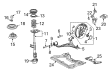
Genuine Mercedes-Benz C320 Control Arm
Suspension Arm- Select Vehicle by Model
- Select Vehicle by VIN
Select Vehicle by Model
orMake
Model
Year
Select Vehicle by VIN
For the most accurate results, select vehicle by your VIN (Vehicle Identification Number).
12 Control Arms found

Mercedes-Benz C320 Front Lateral Link Part Number: 210-350-34-06
$45.60 MSRP: $64.00You Save: $18.40 (29%)
Mercedes-Benz C320 Lower Control Arm Part Number: 203-350-00-06
$75.60 MSRP: $105.00You Save: $29.40 (28%)Ships in 1-2 Business Days
Mercedes-Benz C320 Lower Control Arm Part Number: 202-350-02-06
$78.00 MSRP: $109.00You Save: $31.00 (29%)Ships in 1-2 Business Days
Mercedes-Benz C320 Upper Control Arm Part Number: 204-330-43-11-80
$143.12 MSRP: $199.00You Save: $55.88 (29%)Ships in 1-2 Business Days
Mercedes-Benz C320 Control Arm Part Number: 203-330-16-11
$92.57 MSRP: $129.00You Save: $36.43 (29%)Mercedes-Benz C320 Control Arm Part Number: 203-330-17-11
$98.40 MSRP: $137.00You Save: $38.60 (29%)
Mercedes-Benz C320 Lower Control Arm Part Number: 204-330-20-11-80
$218.82 MSRP: $304.50You Save: $85.68 (29%)Ships in 1-2 Business Days
Mercedes-Benz C320 Lower Control Arm Part Number: 203-330-03-07
$374.40 MSRP: $520.00You Save: $145.60 (28%)Ships in 1-2 Business DaysMercedes-Benz C320 Lower Control Arm Part Number: 203-330-04-07
$366.00 MSRP: $510.00You Save: $144.00 (29%)Ships in 1-2 Business DaysMercedes-Benz C320 Upper Control Arm Part Number: 204-330-44-11-80
$146.72 MSRP: $205.00You Save: $58.28 (29%)Ships in 1-2 Business DaysMercedes-Benz C320 Lower Control Arm Part Number: 204-330-19-11-80
$235.62 MSRP: $326.50You Save: $90.88 (28%)Ships in 1-2 Business Days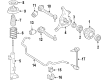
Mercedes-Benz C320 Lower Control Arm Part Number: 203-330-20-11
$218.82 MSRP: $304.50You Save: $85.68 (29%)
Mercedes-Benz C320 Control Arm
Every OEM part goes through strict quality checks. The checks keep you safe and make Control Arm tough. They keep performance the same as your original parts. If your Mercedes-Benz C320 needs OEM parts, visit our catalog. You will find extensive genuine Mercedes-Benz C320 parts. We offer a wide selection at competitive prices, and with clear fit details and simple guidance, choosing what you need is effortless. Each of our parts has a manufacturer's warranty. You will like our simple return policy. We pack and ship fast, and you get your order quickly. Shopping here feels easy and enjoyable.
Mercedes-Benz C320 Control Arm Parts and Q&A
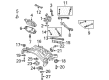
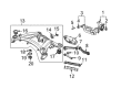
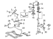
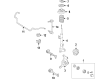
- Q: How to remove and install the lower control arm on Mercedes-Benz C320?A:This is only for the 4MATIC (AWD) models and any fasteners and the corresponding hardware connecting the lower control arm with the subframe has to be removed and replaced to maintain the correct front wheel alignment. The first and second step would be to loosen the wheel bolts so that the front of the car is lifted up and placed on jackstands to ensure it is supported by the frame of the vehicle rather than any part of the suspension. Then take the engine splash shield out underneath the car. When the bi-xenon headlamps are fitted with range adjustors, remove the sensor connection to the lower control-arm on one side, only. Indicate front and rear fitting attachments on the arm, and release tie-rod end when seated in Steering Knuckle. Repeat this procedure by disconnecting the lower control arm balljoint to the steering knuckle; tools to separate balljoints are available in most auto parts stores. Check lower control arm-to-subframe pivot bolts Check grooves by looking at the ends of each mounting bolt where the threads will be visible; note the existence or absence of a grooved mounting bolt which can be used to adjust the vehicle wheel position. When loosening the nut, be sure to hold the lower control arm-to-subframe mounting bolt but be careful avoid turning the control arm mounting bolts and doing so will prevent removal of the small lugs in the center of the arm bushing. Clean out the nut and take the bolt out in a manner that does not disturb the bolts position in the lugged part of the bushing and associated washers. When the bolt does not have any grooves, it is housed between the lugs in the middle of the bushing. We work sidewards with the side tie-rod to the extreme opposite end when undoing the rear pivot bolt, in order to lift it out. Lastly, once the lower control arm is in place, take it in the subframe bracket and slide it in the direction. To install, follow the instructions in reverse order, with a new ball joint stud nut and making sure that all driver screws are tightened to the recommended torque rates with new self-locking nuts wherever possible. Use a floor jack to raise the lower control arm while simulating normal ride height and then use a floor jack to tighten the lower control arm mounting nuts at the sub frame. Fit the wheel and drop vehicle then fasten the wheel bolts to required torque and, where desirable, test and refocus the front wheel end.


