×
- Hello
- Login or Register
- Quick Links
- Live Chat
- Track Order
- Parts Availability
- RMA
- Help Center
- Contact Us
- Shop for
- Mercedes-Benz Parts
My Garage
My Account
Cart
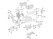
Genuine Mercedes-Benz C350 Piston
Engine Pistons- Select Vehicle by Model
- Select Vehicle by VIN
Select Vehicle by Model
orMake
Model
Year
Select Vehicle by VIN
For the most accurate results, select vehicle by your VIN (Vehicle Identification Number).
3 Pistons found

Mercedes-Benz C350 Piston Part Number: 276-030-52-17
$460.80 MSRP: $855.00You Save: $394.20 (47%)Ships in 1-2 Business DaysMercedes-Benz C350 Piston Part Number: 276-030-53-17-28
$384.00 MSRP: $715.00You Save: $331.00 (47%)Ships in 1-2 Business Days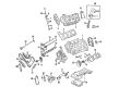
Mercedes-Benz C350 Piston Part Number: 272-030-16-18
$309.60 MSRP: $575.00You Save: $265.40 (47%)Ships in 1-2 Business Days
Mercedes-Benz C350 Piston
Every OEM part goes through strict quality checks. The checks keep you safe and make Piston tough. They keep performance the same as your original parts. If your Mercedes-Benz C350 needs OEM parts, visit our catalog. You will find extensive genuine Mercedes-Benz C350 parts. We offer a wide selection at competitive prices, and with clear fit details and simple guidance, choosing what you need is effortless. Each of our parts has a manufacturer's warranty. You will like our simple return policy. We pack and ship fast, and you get your order quickly. Shopping here feels easy and enjoyable.
Mercedes-Benz C350 Piston Parts and Q&A
- Q: How to remove of the Piston on Mercedes-Benz C350?A:The cylinder head(s) and the oil pan should be removed before the drawing of piston and connecting rod assemblies. On four-cylinder engines the balance shaft assembly must be disassembled so the rod and main bearing caps can be reached. Note for any ridge at the upper limit of ring travel, and when it is there, you must remove it with nail and ridging reamer to the uttermost to avoid piston fracture. Once the ridges have been removed turn the engine such that the crank being is facing up. In the case of four-cylinder engines the balance shaft assembly must be removed. Measure the connecting rod endplay using feeler gauges and per the service limit, have it four-point checked before the main bearing cap assembly is removed and connected rods installed. Make sure that you can differentiate connecting rods and caps without mixing them up. Selectively loosen the connecting rod cap bolts or nuts until they become loosened enough that they can be picked out by hand and remove the number one connecting rod cap and bearing insert without dropping the bearing. Pull the connecting rod/piston assembly out of the top of the engine with a hammer handle of wood or plastic, if needed. Do the same with the other cylinders, measure rod bolt lengths and replace any that are stretched out. The connecting rods and the pistons can then be inspected and overhauled. Prior to changing the piston rings, review the rings end gaps and confirm that the ring side clearance of the piston rings is proper. Prepare the piston/connecting rod assemblies and new ring sets to match at installation. Install the top ring in the preliminary cylinder, align it with the sides of the cylinder and gauge end gap by use of feeler gauges. And, when the gap is wrong, change it prudently. Do the same on all rings and match the rings to the appropriate pistons and cylinders. The rings must be installed in the right order by placing the oil control ring then the middle ring after which comes the top ring, all in the right order. - Do not place a piston/connecting rod assemblies anywhere unless the walls of the cylinder bore are clean, the top of each bore is chamfered, and the crankshaft is fitted. Wash and dry the bearing surfaces of the connecting rod and cap, replace the upper bearing insert and also replace the lower bearing insert in the rod cap without lubricating them. Install the piston ring gaps, lubricate the piston and rings, and roll a piston ring compressor in the process. The piston/connecting rod assembly is then inserted into the bore occupied by the piston ensuring that the connecting rod is lined up with the crankshaft journal. Measure the connecting rod bearing oil clearance with Plastigage, and as required replace the bearing inserts. Once the Plastigage is removed, both sides of the bearing faces should be coated with a layer of grease or engine assembly lube, the connecting rod and cap should be reconnected and the bolts tightened to the recommended torque. Still the rest of the assemblies taking care not to soil them or to hang them upside down. Lastly, turn the crankshaft one full step at a time to verify the absence of binding and again verify the connection rod endplay and adjust as needed.
Related Mercedes-Benz C350 Parts
 Mercedes-Benz C350 Air Filter Box
 Mercedes-Benz C350 Air Temperature Sensor
 Mercedes-Benz C350 Oil Filter Gasket
 Mercedes-Benz C350 Oil Pressure Switch
 Mercedes-Benz C350 Power Steering Cooler
 Mercedes-Benz C350 Power Steering Pump
 Mercedes-Benz C350 Sway Bar Bushing
 Mercedes-Benz C350 Throttle Body
 Mercedes-Benz C350 Valve Stem Oil Seal
 Mercedes-Benz C350 Windshield Wiper Motors